Robotics Integration: What Manufacturing Leaders Need to Know
TL;DR:
- Robotics integration connects hardware, software, and safety into a unified production system, not just a robot. It can improve overall equipment effectiveness by up to 30 percent and increase production capacity significantly. Success requires early co-design, standardized protocols, thorough validation, and future-proof architecture from the start.
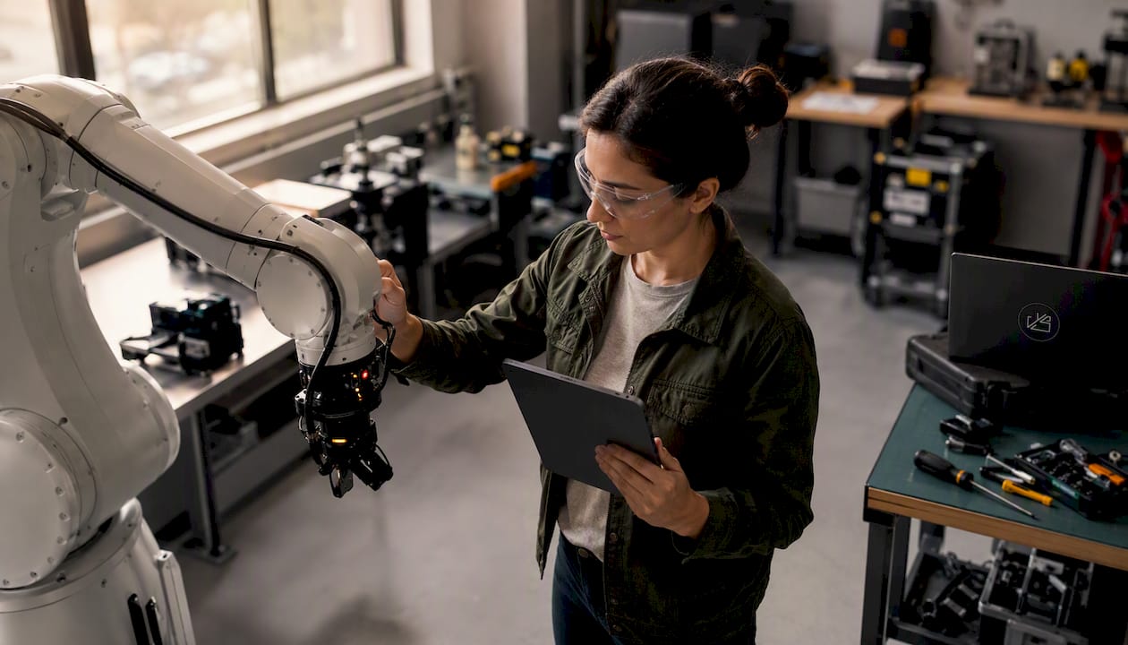
Robotics integration is the engineering process of connecting robots, controllers, sensors, vision systems, safety devices, and software into a coordinated production system that performs specified tasks reliably and repeatedly. Buying a robot is not the same thing. A standalone arm sitting next to a conveyor is just expensive equipment. An integrated system ties that arm to your PLC, your MES, your safety architecture, and your quality data, so every component acts as part of a single, purposeful whole.
The operational payoff is real. Integrated systems connecting robotics, vision, conveyors, PLCs, and MES can increase OEE by 20–30% and production capacity by up to 25% in some studies. A robot with integrated vision and closed-loop control can detect a defect and trigger an upstream parameter adjustment automatically, without a human in the loop. That is the difference between a productivity tool and a driver of digital transformation.
TLDR:
- Robotics integration connects hardware, software, and safety into one coordinated system, not just a robot purchase.
- Measurable gains include OEE improvements of 20–30% and production capacity increases up to 25% in some studies.
- Success depends on hardware/software co-design, clear interface contracts, and phased commissioning, not just robot selection.
Table of Contents
- What makes up a complete robotics integration system?
- How does the integration process actually unfold?
- Where does robotics integration deliver the most value?
- How do you build the business case for robotics integration?
- Should you integrate in-house or hire a systems integrator?
- What risks should you plan for, and how do you mitigate them?
- How do you future-proof an integration from the start?
- A real-world example: cobot integration for CNC machine tending
- Key Takeaways
- What actually makes integrations succeed in practice
- Yslootahtech can help you move from concept to commissioned system
- Useful sources and standards for further reading
What makes up a complete robotics integration system?
Most integration failures trace back to the same root cause: someone treated the robot as the system instead of one component inside it. The actual stack has seven distinct layers, and a gap in any one of them creates either a safety hazard or a performance shortfall.
| Component | Function |
|---|---|
| Robot arm / cobot | Executes motion; payload, reach, and speed define task fit |
| End-of-arm tooling (EOAT) | Grippers, welding torches, or inspection heads that interact with the part |
| Controller | Interprets programs and sends motion commands to the robot |
| PLC / fieldbus | Coordinates the robot with conveyors, fixtures, and peripheral equipment |
| Vision system | Locates parts, verifies orientation, and triggers quality checks |
| Sensors and I/O | Proximity, force/torque, and safety sensors that give the system situational awareness |
| Safety devices | Light curtains, area scanners, safety-rated PLCs, and interlocks that protect people |
| Integration software / HMI | Supervisory layer for operator control, alarming, and data logging |
| MES / ERP link | Connects the cell to production scheduling, traceability, and quality records |
The interoperability layer is where many projects quietly fail. Industrial Ethernet protocols, specifically EtherNet/IP, PROFINET, and EtherCAT, are the dominant communication standards in U.S. manufacturing today. Fieldbus options like DeviceNet and PROFIBUS still appear in legacy plants. Choosing a robot or PLC that does not natively support your plant's protocol means added gateways, added latency, and added failure points.
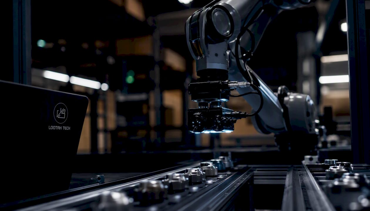
Integration gives robots context: with vision and control working together, a defect detected at the inspection station can automatically trigger adjustments to welding parameters two stations upstream. That closed-loop correction is only possible when every layer of the stack communicates via a shared protocol with defined timing.
Pro Tip: Before selecting any robot model, document your plant's existing fieldbus and safety PLC vendor. Mismatched protocols discovered after purchase add weeks and real cost to commissioning.
How does the integration process actually unfold?
Robotic integration follows a phased sequence: concept and requirements, hardware/software co-design, safety validation, installation, commissioning, and workforce training. The phases are not optional, and skipping or compressing any one of them is where projects go sideways.

| Phase | Typical Duration | Key Deliverables |
|---|---|---|
| Concept & requirements | 2–4 weeks | Process spec, cycle time targets, safety risk assessment |
| Robot & EOAT selection | 1–3 weeks | Vendor shortlist, payload/reach confirmation, protocol check |
| HW/SW co-design | 4–12 weeks | Mechanical layout, PLC program, HMI screens, interface contracts |
| Safety validation | 1–3 weeks | Risk assessment sign-off, safety PLC configuration, guarding design |
| Installation | 1–4 weeks | Mechanical and electrical build, network commissioning |
| FAT / SAT & run-off | 1–3 weeks | Acceptance test results, cycle time verification, fault-recovery test |
| Operator training | 1–2 weeks | Trained operators, maintenance procedures, restart documentation |
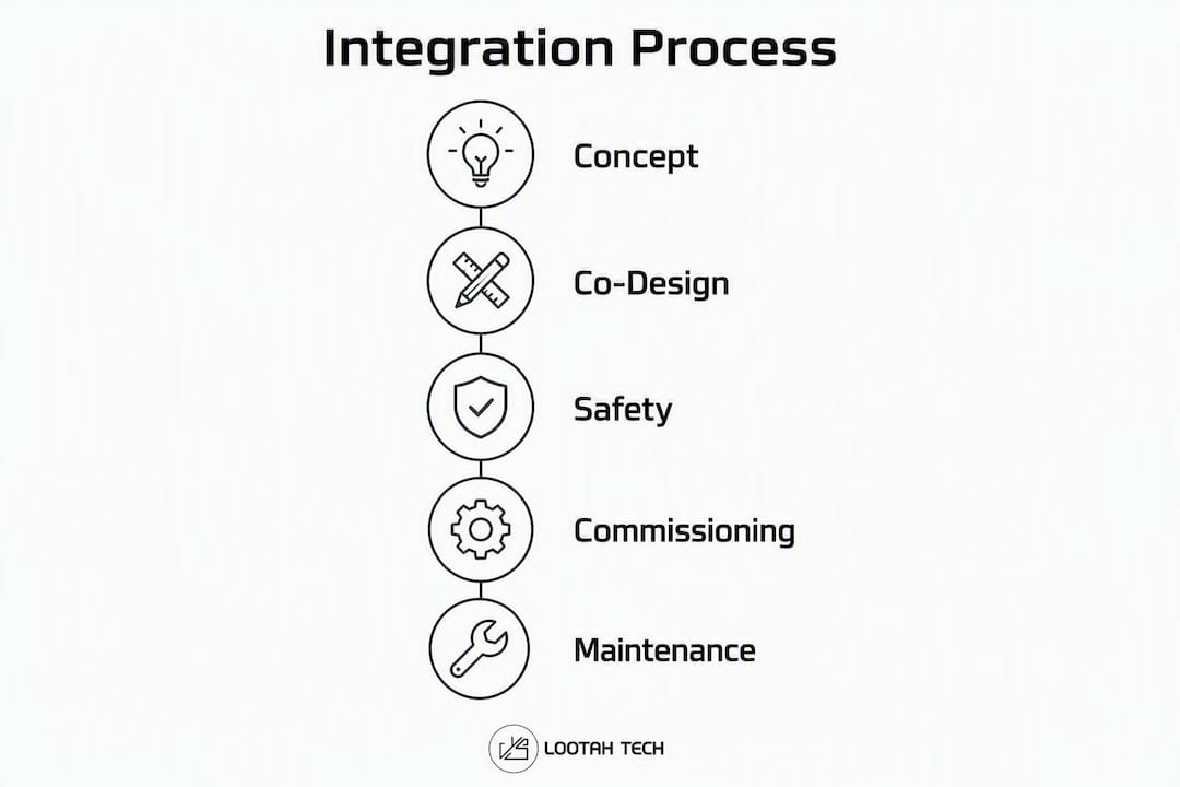
Duration ranges above reflect small-to-medium projects. Large, multi-cell installations with MES integration can run 6–18 months end to end.
The phase that most teams underestimate is co-design. Hardware/software co-design prevents late-stage discoveries of hardware limits and avoids the expensive redesign cycles that happen when a mechanical engineer finalizes a fixture before the controls engineer has defined the I/O requirements. The biggest misconception in the industry is designing hardware first and adding software later. Projects that do it that way almost always hit a wall during commissioning.
The deliverables checklist for procurement acceptance should include:
- Signed-off risk assessment and safety validation report
- FAT and SAT test records with pass/fail criteria
- Fault-recovery and restart procedures in the operator manual
- Cycle time verification against the original spec
- Changeover procedure documentation for each product variant
- As-built electrical and mechanical drawings
Commissioning is the moment where design meets reality. Many project failures stem from neglecting fault-recovery, changeover, and maintainability during the design phase, and those gaps only surface when the system runs for the first time under production conditions.
Where does robotics integration deliver the most value?
The applications below represent the highest-volume use cases in U.S. manufacturing, mapped to the industries where integration constraints are most relevant.
- Machine tending (CNC, injection molding, stamping): The robot loads and unloads parts on a fixed cycle. Integration with the machine's M-code or digital I/O is required for handshake signals. Cobots fit low-mix, lower-volume cells; industrial robots suit high-speed, high-volume lines.
- Palletizing and depalletizing: Vision-guided picking from mixed or unstable layers is now standard in food and beverage and distribution. Integration with the WMS determines pallet patterns and label placement in real time.
- Arc and spot welding: Automotive and heavy equipment manufacturers rely on tight integration between the robot controller and the welding power source. Weld parameter data feeds back to the MES for traceability.
- Pick-and-place and assembly: Electronics and consumer goods plants use vision-guided pick-and-place for PCB handling and small-part assembly. Part presentation consistency is critical here.
- Automated inspection: Pharma and medical device manufacturers integrate vision systems directly into the robot cell for 100% in-line inspection, replacing manual sampling. Defect data writes directly to the batch record.
- Packaging and case packing: Food and beverage and e-commerce operations integrate robots with checkweighers, date coders, and conveyor systems. The integration challenge is synchronizing variable-speed upstream lines.
- Material handling and AGV coordination: Warehousing and distribution centers integrate autonomous mobile robots (AMRs) with WMS and supervisory software. Software is the differentiator here: predictive maintenance, interoperability with the WMS, and command-and-control layers determine whether the system scales.
Cobots fit best where operators work in close proximity, cycle times are moderate, and product mix is high. Industrial robots are the right call when speed, payload, or precision exceeds cobot ratings, or when the process runs lights-out.
How do you build the business case for robotics integration?
The business case for a robotics integration project rests on four measurable categories: throughput, quality, safety, and labor reallocation. Vague claims about "efficiency gains" do not survive a CFO review. Specific KPIs do.
KPIs to track from day one:
- Overall Equipment Effectiveness (OEE) before and after
- Cycle time per unit
- First-pass yield / defect rate
- Unplanned downtime hours per month
- Recordable safety incidents in the cell
- Labor hours per unit produced
- Changeover time per product variant
Sample ROI calculation outline:
- Baseline the current cost per unit (labor, scrap, rework, downtime).
- Estimate post-integration cost per unit using the vendor's cycle time spec and your scrap/defect targets.
- Calculate annual savings: (cost reduction per unit) × (annual volume).
- Sum total project cost: robot hardware, EOAT, safety guarding, PLC and networking, engineering and integration hours, commissioning, training, and first-year maintenance.
- Payback period = total project cost ÷ annual savings.
- For a fuller picture, calculate NPV over a 5–7 year horizon using your company's discount rate.
Main cost components to budget:
- Robot hardware and EOAT (grippers, sensors, quick-change tooling)
- Safety fencing, light curtains, area scanners, and safety-rated PLC
- PLC, networking hardware, and industrial Ethernet cabling
- Engineering and systems integration labor hours
- FAT/SAT commissioning and run-off
- Operator and maintenance training
- Annual maintenance contract and spare parts inventory
Pro Tip: Build your ROI model around conservative cycle time estimates from the integrator's FAT data, not the robot manufacturer's theoretical maximum. The gap between spec-sheet speed and real-world throughput is where most payback projections go wrong.
For a deeper look at the ROI framework, the advantages of robotics in business guide covers payback modeling and KPI benchmarks in more detail.
Should you integrate in-house or hire a systems integrator?
The answer depends on four variables: project complexity, process stability, internal technical capacity, and how much downtime risk you can absorb. Neither option is universally better.
| Decision Factor | In-House Integration | Third-Party Integrator |
|---|---|---|
| Project complexity | Simple, single-robot cells with stable processes | Multi-robot, multi-protocol, or greenfield installations |
| Process stability | Well-documented, low-variation processes | New processes or high-mix environments |
| Internal staff | Experienced controls engineers on staff | Limited automation engineering capacity |
| Time-to-value | Slower ramp if staff are learning | Faster with experienced integrators |
| Cybersecurity | Easier to control network access | Requires clear network segmentation agreements |
| Vendor lock-in risk | Lower | Higher without modular acceptance criteria in the SOW |
Cobots lower the entry barrier for simple tasks, but manufacturers must honestly assess process stability before choosing in-house integration. A cobot with a teach pendant is not a substitute for a controls engineer when the process involves multiple I/O handshakes, vision, and MES connectivity.
Questions to ask prospective integrators:
- Can you provide references from projects in our industry with similar cycle time and protocol requirements?
- Who owns the PLC and robot programs at project close, and what is the license model?
- How do you handle scope changes during co-design, and what is your change-order process?
- What does your FAT/SAT acceptance test include, and will you test fault-recovery and changeover scenarios?
- What is your post-commissioning support model and response time?
Red flags to watch for: integrators who quote without a site visit, who cannot name the specific safety standard they will design to (ANSI/RIA R15.06 or ISO 10218), or who propose a fixed-price contract with no defined acceptance criteria.
Pilot projects reduce risk on both sides. Define a single cell or process as the pilot scope, agree on acceptance criteria before work begins, and require modular program architecture so the code can be extended or handed to another integrator if needed.
What risks should you plan for, and how do you mitigate them?
Robotic systems integration spans mechanical, electrical, software, safety, and workforce domains. A failure in any one of those domains can create latent hazards or sustained performance shortfalls. The risks below are the ones that most consistently derail projects.
Top implementation risks and mitigations:
- Interoperability gaps: Subsystem teams build components that cannot communicate. Mitigation: require formal interface contracts in the SOW that specify data formats, timing, error codes, and boundary conditions before mechanical design begins.
- Part presentation failures: Inconsistent part orientation or accumulation starves the robot and kills OEE. Mitigation: treat conveyor accumulation, vision-based orientation, and buffer design as first-class engineering tasks, not afterthoughts.
- Safety compliance gaps: Missing or misconfigured safety devices create OSHA recordable incidents and regulatory exposure. Mitigation: conduct a formal risk assessment per ANSI/RIA R15.06 and ISO 10218-2 before installation, and validate safety PLC logic during FAT.
- Cybersecurity exposure: Robot controllers and PLCs connected to plant networks are attack surfaces. Mitigation: segment the automation network from the corporate IT network, require the integrator to document all remote access credentials, and disable unused ports.
- Unplanned downtime during cutover: Live production lines cannot absorb extended commissioning overruns. Mitigation: schedule FAT at the integrator's facility before shipment, and plan SAT during a planned maintenance window.
Commissioning and recovery best practices:
- Run FAT at the integrator's facility with your controls engineer present and your actual parts.
- Test every fault-recovery scenario during FAT, not just the happy path.
- Validate changeover procedures for each product variant before SAT sign-off.
- Require modular program structure so maintenance technicians can isolate and restart individual stations without resetting the entire cell.
- Document restart procedures in plain language in the operator manual, not just in the PLC comments.
Compliance checkpoints: ANSI/RIA R15.06 governs industrial robot safety in the United States. ISO 10218-1 and 10218-2 cover robot design and integration requirements. OSHA 29 CFR 1910.217 and the General Duty Clause apply to robot cell guarding. NFPA 79 governs electrical safety for industrial machinery. These are not optional references; they are the standards your integrator should be designing to by default.
How do you future-proof an integration from the start?
The integrations that age well share one characteristic: the team treated software architecture and hardware architecture as a single design problem, not two sequential ones. Hardware/software co-design is the practice of developing mechanical layouts, control logic, and software interfaces in parallel so that hardware constraints inform software design and vice versa.
Best practices for future-proof integration:
- Modular software architecture: Write PLC and robot programs as independent, reusable function blocks. A cell that adds a second robot or a new product variant should require configuration changes, not a full rewrite.
- Standard communication protocols: Specify EtherNet/IP, PROFINET, or EtherCAT in the SOW. Proprietary OEM communication layers create vendor lock-in and make MES integration harder.
- Telemetry and IIoT connectivity: Require OPC-UA or MQTT data output from the robot controller and PLC so predictive maintenance and OEE dashboards can consume real-time data without custom middleware.
- Swap-out tooling design: Specify quick-change EOAT with repeatable mechanical and electrical interfaces so product changeovers take minutes, not hours.
- API access to telemetry: Contractually require that the integrator provides documented API access to all telemetry data. Without this, you cannot build predictive maintenance or connect to a future MES upgrade.
SOW language that protects your investment:
- Require acceptance tests that include changeover and fault-recovery scenarios, not just cycle time at steady state.
- Specify that all source code (PLC, robot, HMI) is delivered as part of project close with no license restrictions.
- Include a modular acceptance clause: the system must pass acceptance for each product variant independently.
On the middleware question: ROS 2 (Robot Operating System) is gaining traction in research and flexible manufacturing environments where open middleware matters more than vendor support. For most U.S. production environments, proprietary OEM stacks with standard industrial Ethernet remain the lower-risk choice. ROS 2 makes sense when you need multi-vendor robot coordination or when your team has the software engineering depth to maintain it.
Pro Tip: Require OPC-UA data output in your RFQ. It costs almost nothing to specify upfront and saves significant integration effort when you connect to a future MES, ERP, or AI-driven predictive maintenance platform.
A real-world example: cobot integration for CNC machine tending
A mid-size precision machining shop running two CNC lathes faced a recurring problem: skilled operators spent roughly 40% of their shift on load/unload cycles, leaving them unavailable for setup, inspection, and quality work. The decision was made to integrate a cobot for machine tending on one lathe as a pilot.
Project milestones:
- Requirements and risk assessment (2 weeks): cycle time target set at 28 seconds load/unload, safety risk assessment completed per ANSI/RIA R15.06.
- Co-design phase (6 weeks): cobot model selected based on payload and reach; EOAT designed in parallel with the fixture; PLC I/O map and M-code handshake defined before mechanical build began.
- FAT at integrator facility (1 week): full cycle tested with actual parts, fault-recovery scenarios validated, changeover procedure for a second part family documented.
- Installation and SAT (1 week): cell installed during a planned maintenance weekend; SAT completed against the agreed acceptance criteria.
- Operator training (3 days): two operators and one maintenance technician trained on teach pendant, restart procedures, and EOAT changeover.
Before and after KPI snapshot:
| KPI | Before | After |
|---|---|---|
| Operator load/unload time | ~40% of shift | ~5% of shift (monitoring only) |
| Machine utilization | 61% | 83% |
| Defect rate (dimensional) | 2.1% | 0.8% |
| Changeover time (part family) | N/A | 12 minutes |
Lessons learned:
- Part presentation was the hardest problem. The incoming parts bin required a redesigned accumulation conveyor and a vision-based orientation check before the cobot could pick reliably. Robot programming took two days; part presentation engineering took two weeks.
- Fault-recovery procedures written during FAT saved the maintenance team hours on the first production fault. Without them, the restart would have required the integrator on-site.
- The M-code handshake with the CNC controller needed three revisions during co-design because the machine builder's documentation was incomplete. Starting co-design earlier would have caught this before mechanical build.
Pro Tip: Always request the CNC machine builder's full I/O and M-code documentation before the co-design phase begins. Incomplete machine documentation is the single most common cause of cobot-to-machine handshake delays.
Key Takeaways
Robotics integration succeeds when hardware, software, and safety are co-designed from the start, not assembled in sequence after the robot is already on the floor.
| Point | Details |
|---|---|
| Integration vs. standalone robot | An integrated system connects robots, PLCs, vision, safety, and MES into one coordinated whole, not just a robot purchase. |
| OEE and capacity gains | Integrated systems can increase OEE by 20–30% and production capacity by up to 25% in some studies when all stack layers communicate correctly. |
| Co-design is non-negotiable | Hardware and software must be designed in parallel; sequential design is the leading cause of costly commissioning failures. |
| Make-vs-buy rule of thumb | Hire a systems integrator for multi-robot, multi-protocol, or greenfield projects; in-house integration fits simple, stable, single-cell tasks. |
| Yslootahtech's role | Yslootahtech delivers robotics integration, AI-driven vision, and lifecycle support for manufacturers pursuing digital transformation. |
What actually makes integrations succeed in practice
Most integration projects that fall short share the same pattern: the team locked in the mechanical design before the controls engineer had defined the I/O requirements, and the software team was handed a finished fixture to work around. The co-design principle sounds obvious until you watch a project skip it and spend three weeks reworking a fixture during commissioning.
The other thing that consistently separates successful projects from expensive lessons is the interface contract. Specifying data formats, timing, error codes, and boundary conditions between subsystems before anyone writes a line of code or bends a piece of steel is the single highest-leverage action a project manager can take. It is not glamorous, but it is what prevents the robot team and the conveyor team from building components that cannot talk to each other.
Yslootahtech brings robotics development, AI and machine learning, and enterprise application integration together under one engagement model, which means the software architecture and the hardware requirements get resolved in the same conversation rather than across two separate vendor relationships. For manufacturers evaluating their first integration or scaling an existing cell, that coordination is where the real risk reduction happens. The role of robotics in business goes well beyond the cell floor, and the teams that treat it that way from day one tend to build systems that actually scale.
Yslootahtech can help you move from concept to commissioned system
Manufacturers who have read this far are usually at one of two decision points: they know they need to integrate but are not sure where to start, or they have a project scoped and need a technology partner who can handle the software complexity without adding a third vendor to the mix.
Yslootahtech delivers end-to-end robotics integration support, from requirements and co-design through commissioning and workforce training, with AI and machine learning capabilities built into the same engagement. That means vision systems, predictive maintenance pipelines, and MES connectivity are designed alongside the mechanical and controls architecture, not bolted on afterward. For manufacturers in the United States looking to move from a standalone robot to a fully integrated production system, the AI and machine learning services page covers the supervisory software and data pipeline capabilities that make integration future-proof. To discuss your specific project requirements, contact Yslootahtech directly through the robotics services page and request a discovery consultation.
Useful sources and standards for further reading
- ANSI/RIA R15.06 — the primary U.S. standard for industrial robot safety, covering risk assessment and safeguarding requirements
- ISO 10218-1 and ISO 10218-2 — international standards for robot design and integration safety
- OSHA Robotics Safety — OSHA guidance on robot cell guarding and General Duty Clause obligations
- Robotic Systems Integration and Deployment Best Practices — practitioner-level guidance on interface contracts, safety validation, and commissioning
- Why Integrated Robotics Are Essential to High-Performance Warehouses — warehousing-specific integration requirements and software-as-differentiator argument